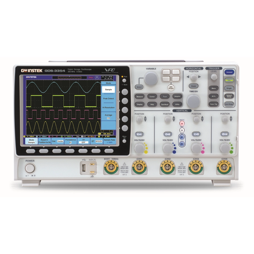
VPO – Visual Persistence Oscilloscope
| 원산지 | 중화민국 (대만) · REPUBLIC OF CHINA (TAIWAN) · 中華民國 (臺灣) |
|---|---|
| 제조사 | GOOD WILL INSTRUMENT CO., LTD. |
| 브랜드 | GW INSTEK |
| 무게 | 1kg |
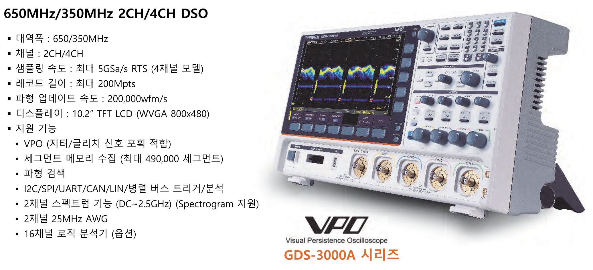
VPO – Visual Persistence Oscilloscope
GDS-3000A 시리즈 – 650MHz/350MHz 2CH/4CH DSO
- 대역폭 : 650/350MHz
- 채널 : 2CH/4CH
- 샘플링 속도 : 최대 5GS/s RTS (4채널 모델)
- 레코드 길이 : 최대 200Mpts
- 파형 업데이트 속도 : 200,000wfm/s
- 디스플레이 : 10.2″ TFT LCD (WVGA 800x480)
- 지원 기능
- VPO (지터/글리치 신호 포획 적합)
- 세그먼트 메모리 수집 (최대 490,000 세그먼트)
- 파형 검색
- 12C/SPI/UART/CAN/LIN/병렬 버스 트리거/분석
- 2채널 스펙트럼 기능 (DC~2.5GHz) (Spectrogram 지원)
- 2채널 25MHz AWG
- 16채널 로직 분석기 (옵션)
GDS-3352A
: 10.2″ LCD, 200Mpts메모리, 5GSa/s HalfCH; 2.5GSa/s FullCH; 듀얼채널 25MHz AWG; 2.5GHz 스펙트럼; 시리얼버스디코딩; USB;RS232;LAN
GDS-3354A
: 10.2″ LCD, 200Mpts메모리, 5GSa/s HalfCH; 2.5GSa/s FullCH; 듀얼채널 25MHz AWG; 2.5GHz 스펙트럼; 시리얼버스디코딩; USB;RS232;LAN
GDS-3652A
: 10.2″ LCD, 200Mpts메모리, 5GSa/s HalfCH; 2.5GSa/s FullCH; 듀얼채널 25MHz AWG; 2.5GHz 스펙트럼; 시리얼버스디코딩; USB;RS232;LAN
GDS-3654A
: 10.2″ LCD, 200Mpts메모리, 5GSa/s HalfCH; 2.5GSa/s FullCH; 듀얼채널 25MHz AWG; 2.5GHz 스펙트럼; 시리얼버스디코딩; USB;RS232;LAN
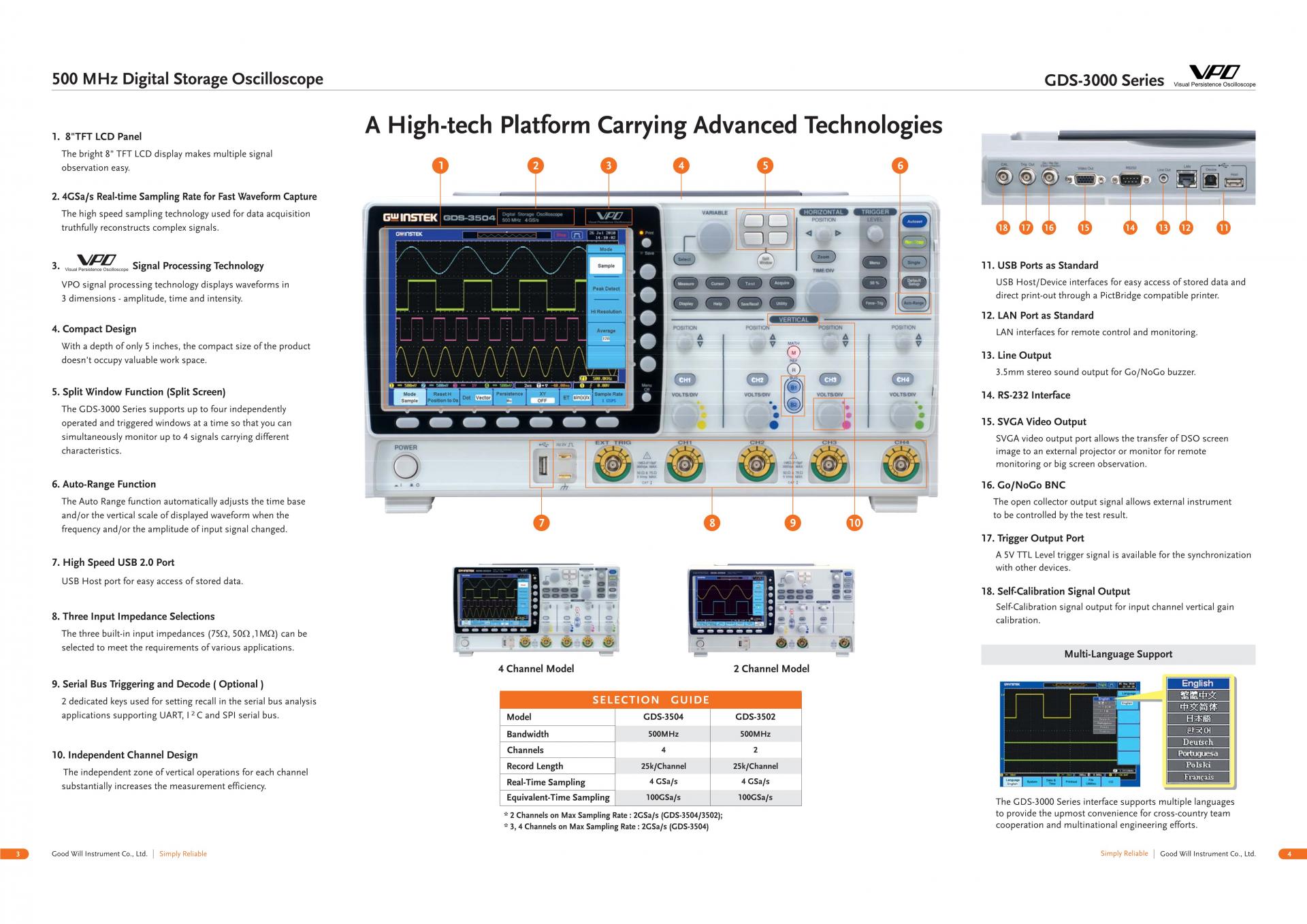
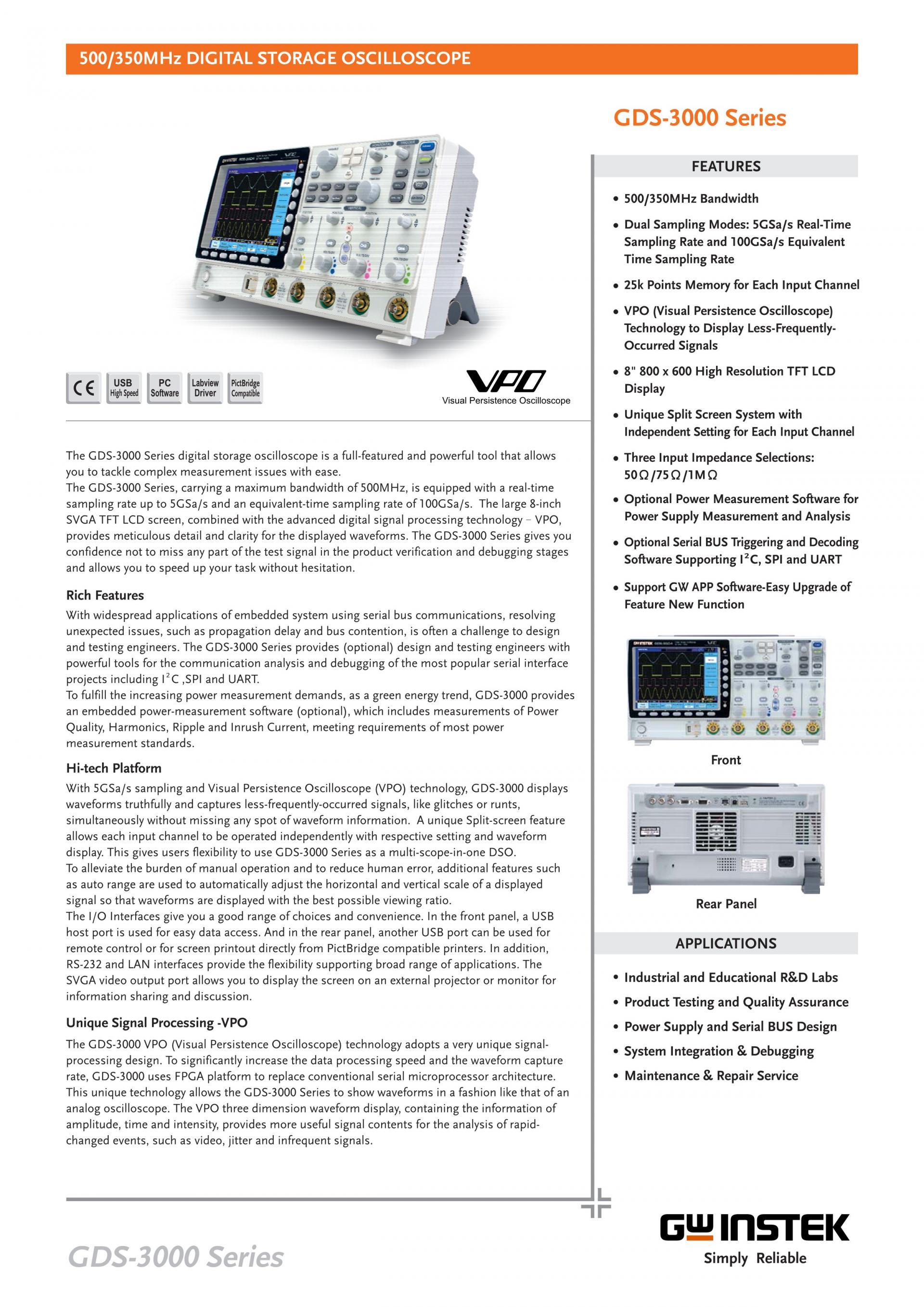
A Hi-tech DSO Platform
The GDS-3000 Series is a platform of 4-input channels, 500MHz bandwidth, 5GSa/s sampling rate, and VPO waveform display. The split screen feature has been designed to meet the requirements of multi-window & multi-signal tests in the research and the manufacturing fields. The optional power analysis software and the optional serial bus analysis software are available to facilitate the engineer's tasks in testing and manufacturing of the associated products.
The differential probe, GDP-025, GDP-050 & GDP-100, and current probes, GCP-020, GCP-100 and GCP-530 & GCP-1030, are coming along with the GDS-3000 Series to provide total solutions for a wide variety of applications in the industry, service and education market sectors. The GDS-3000 Series, a high-tech platform carrying thoughtful features, brings very high customer value to both general purpose market and professional market.
GDS-3502
: 500MHz, 2-ChannelVisual Persistence Oscilloscope
GDS-3504
: 500MHz, 4-ChannelVisual Persistence Oscilloscope
액세서리 • Accessories
| Accessory | |
| User manual CD x 1 , Power cord x1 | |
| GTP-151R | 150MHz(10:1) passive probe for GDS-3152/ 3154 (per channel) |
| GTP-251R | 250MHz(10:1) passive probe for GDS-3252/ 3254 (per channel) |
| GTP-351R | 350MHz(10:1) passive probe for GDS-3352/ 3354 (per channel) |
| GTP-501R | 500MHz(10:1) passive probe for GDS-3502/ 3504 (per channel) |
| Optional Accessories | |
| GUG-001 | GPIB to USB adapter |
| GTP-033A | 35MHz 1:1 passive probe |
| GTP-352R | 350MHz(20:1) passive probe |
| GDP-025 | 25MHz high voltage differential probe |
| GDP-050 | 50MHz 25MHz high voltage differential probe |
| GDP-100 | 100MHz 25MHz high voltage differential probe |
| GCP-005 | 1kHz/5A Current probe |
| GCP-020 | 10kHz/200A Current probe |
| GCP-100 | 100KHz/100A Current probe |
| GCP-530 | 50MHz/ 30A Current probe |
| GCP-1030 | 100MHz/ 30A Current probe |
| GCP-206P | Power supply for current probe (2 input channels) |
| GCP-425P | Power supply for current probe (4 input channels) |
| GTL-248 | GPIB Cable, Double Shielded, 2000mm |
| GTL-251 | USB-GPIB Adapter, GPIB-USB-HS, USB 2.0, Hi-Speed USB compliance, 2000mm |
| GSC-008 | Soft Carrying Case |
| GTL-110 | Test lead, BNC to BNC connector |
| GTL-232 | RS-232C cable, 9-pin female to 9-pin female, Null Modem for computer |
| GTL-246 | USB 2.0 cable, A-B type cable 4P, 1800mm |
| GRA-411 | Rack Adapter Panel |
| GDB-03 | Oscilloscope Education and Training Kit |
| GKT-100 | Deskew fixture |
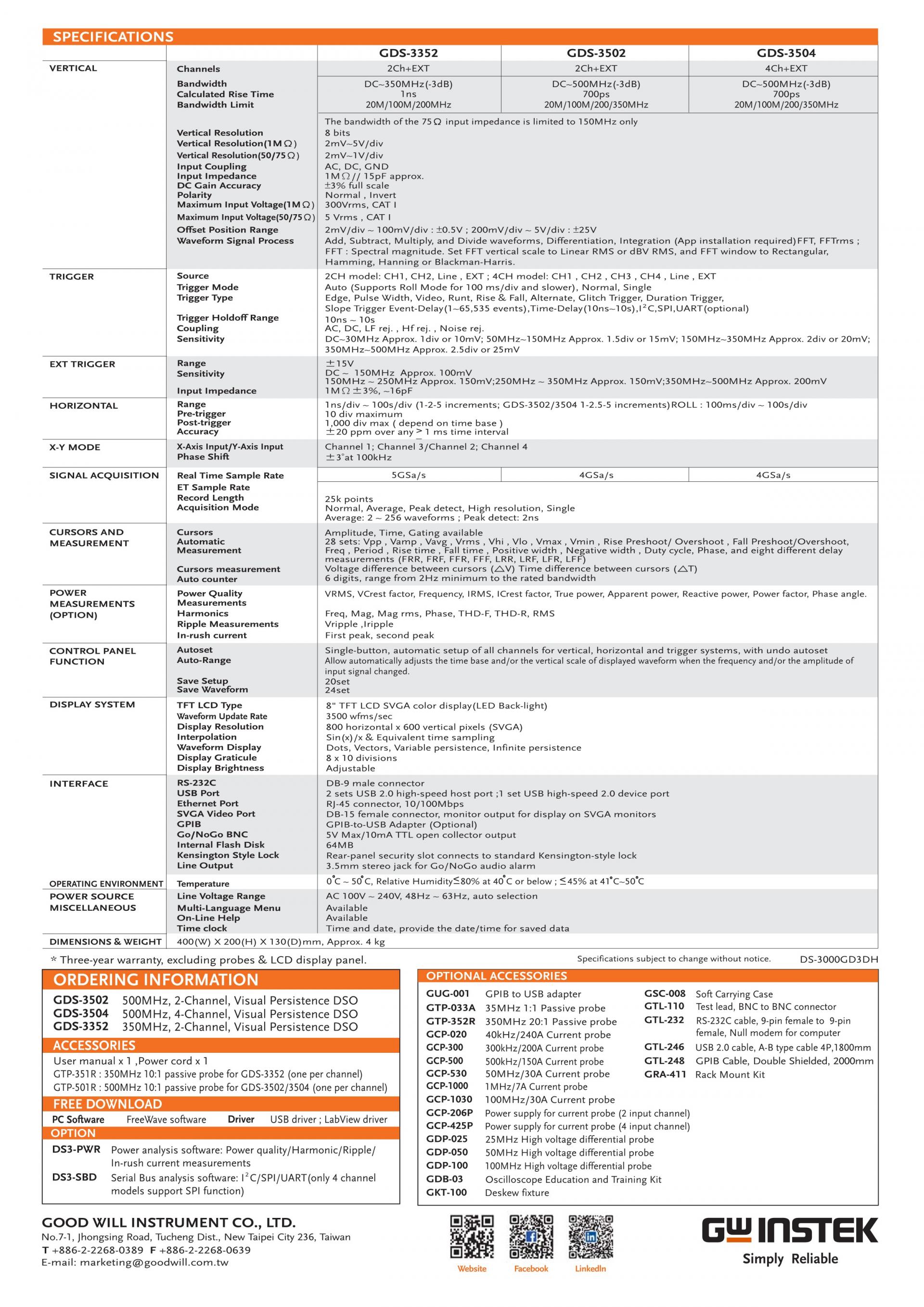
GDS-3000 사양 • Specifications
The specifications apply when the GDS-3000 is powered on for at least 30 minutes under +20°C - +30°C
Model-specific | ||
GDS-3502 | ||
Channels | Bandwidth | Calculated Rise Time |
2 + Ent | DC - 500MHz (−3dB) | 700ps |
GDS-3504 | ||
Channels | Bandwidth | Calculated Rise Time |
4 + Ext | DC - 500MHz (−3dB) | 700ps |
The bandwidth of the 75Ω input impedance is limited to 150MHz only. | ||
Common | |
Vertical | |
Resolution Sensitivity | 8 bit @1MΩ : 2mV - 5V/div @20/75Ω : 2mV~1V/div |
Input Coupling | AC, DC, GND |
Input Impedance | 1MΩ // 15pF |
DC Gain Accuracy | ±3% full scale |
Polarity | Normal & Invert |
Maximum Input Voltage | @1MΩ : 300Vrms, CAT I @20/75Ω: 5 Vrms max |
Offset Position Range | 2mV/div ~ 100mV/div : ±0.5V 200mV/div ~ 5V/div : ±25V |
Bandwidth Limit | Dependent on the oscilloscope bandwidth(BW) BW=150: Full/20MHz BW=250: Full/20MHz/100MHz BW=350: Full/20MHz/100MHz/200MHz BW=500: Full/20MHz/100MHz/200MHz/350MHz |
Waveform Signal Process | Add, subtract, multiply, and divide waveforms, FFT, FFTrms, Integration*, Differentiation* *: App installation required. |
FFT:Spectral magnitude. Set FFT Vertical Scale to Linear RMS or dBV RMS, and FFT Window to Rectangular, Hamming, Hanning, or Blackman‐Harris. | |
Trigger | |
Sources | CH1, CH2, CH3, CH4, Line, EXT |
Modes | Auto (supports Roll Mode for 100 ms/div and slower), Normal, Single Sequence |
Type | Edge, Pulse Width(Glitch), Video, Pulse Runt, Rise & Fall(Slope), Alternate, Event‐Delay(1~65535 events), Time‐Delay(Duration)(10ns~10s), I2C*, SPI*, UART* *optional Runt:Trigger on a pulse that crosses one threshold but fails to cross a second threshold before crossing the first again. SPI (optional):Trigger on SS, MOSI, MISO, or MOSI and MISO on SPI buses. I 2C (optional):Trigger on Start, Repeated Start, Stop, Missing ACK, Address (7 or 10 bit), Data, or Address and Data on I2C buses. UART (optional): Trig ger on Tx Start Bit, Rx Start Bit, Tx End of Packet, Rx End of Packet, Tx Data, Rx Data, Tx Parity Error, and Rx Parity Error. |
Holdoff range | 10ns to 10s |
Coupling | AC, DC, LF rej., Hf rej., Noise rej. |
Sensitivity | GDS‐31XX ~ GDS‐33XX: DC ~ 50MHz Approx. 1div or 10mV |
GDS‐350X: DC ~ 50MHz Approx. 1div or 1.0mV | |
External Trigger | |
Range | ±15V |
Sensitivity | GDS‐31XX ~ GDS‐33XX: DC ~ 150MHz Approx. 100mV 150MHz ~ 250MHz Approx. 150mV 250MHz ~ 350MHz Approx. 150mV 350MHz ~ 500MHz Approx. 200mV |
Input Impedance | 1MΩ±3%, ~16pF |
Horizontal | |
Timebase Range | GDS‐315X, GDS‐325X, GDS‐335X: 1ns/div ~ 100s/div (1‐2‐5 increments); ROLL : 100ms/div ~ 100s/div |
GDS‐350X: 1ns/div ~ 100s/div (1‐2.5‐5 increments); ROLL : 100ms/div ~ 100s/div | |
Pre‐trigger | 10 div maximum |
Post‐trigger | 1000 div maximum. The number of divisions depends on the time division. |
Timebase Accuracy | ±20 ppm over any ≧1 ms time interval |
X‐Y Mode | |
X‐Axis Input | Channel 1; Channel 3 |
Y‐Axis Input | Channel 2; Channel 4 |
Phase Shift | ±3° at 100kHz |
Signal Acquisition | |
Real Time Sample Rate | 150/250/350MHz models: 5GSa/s (MAX) 150/250MHz models with 2CH: 2.5GSa/s 500MHz models: 4GSa/s (MAX), 2GSa/s per channel |
ET Sample Rate | 100GSa/s maximum for all models |
Record Length | 25k points / channel |
Acquisition Mode | Normal, Average, Peak Detect, High Resolution, Single Sequence |
Peak (Glitch) Detection | 2ns (MAX) |
Normal: Acquire sampled values. Average: From 2 to 256 waveforms included in average. Peak Detect: Captures glitches as narrow as 2 ns at all sweep speeds Hi‐Res: Real‐time boxcar averaging reduces random noise and increases vertical resolution | |
Cursors and Measurement | |
Cursors | Amplitude, Time, Gating available |
Automatic Measurement | 28 sets: Vpp, Vamp, Vavg , Vrms, Vhi, Vlo, Vmax, Vmin, Rise Preshoot/Overshoot, Fall Preshoot/Overshoot, Freq, Period, Rise Time, Fall Time, Positive Width, Negative Width, Duty Cycle, and nine different delay measurements (FRR, FRF, FFR, FFF, LRR, LRF, LFR, LFF, Phase) |
Cursors measurement | Voltage difference between cursors (∆V) Time difference between cursors (∆T) |
Auto counter | 6 digits, range from 2Hz minimum to the rated bandwidth |
Power Measurements (Option) | |
Power Quality Measurements | V RMS, I RMS, True Power, Apparent Power, Reactive Power, Frequency, Power Factor, Phase Angle, V Crest Factor, I Crest Factor, (+)V Peak, (‐)V Peak, (+)I Peak, (‐)I Peak, DC Voltage, DC Current, Impedance, Resistance, Reactance |
Harmonics | Frequency (Hz), Magnitude (%), Mag. RMS (A), Phase (˚), Limit (A), Limit (%), Pass | Fail, Max all , Windows (A), 200% Limit, POHC Limit, THD‐F, THD‐R, RMS, Overall, POHC, POHL, Input Power, Power Factor, Fundamental Current, Harmonic 3, Harmonic 5 |
Ripple Measurements | Ripple, Noise |
In‐rush current | First peak, Second peak |
Control Panel Function | |
Autoset | Single‐button, automatic setup of all channels for vertical, horizontal and trigger systems, with undo autoset |
Auto‐Range | allow you to quickly move from test point to test point without having to reset the oscilloscope for each test point |
Save Setup | 20 sets |
Save Waveform | 24 sets |
Display | |
TFT LCD Type | 8″ TFT LCD SVGA color display |
Display Mode | YT, XY |
Display Resolution | 800 horizontal × 600 vertical pixels (SVGA) |
Interpolation | Sin(x)/x & Equivalent Time Sampling |
Waveform Display | Dots, vectors, variable persistence, infinite persistence |
Display Graticule | 8 x 10 divisions |
Waveform Update Rate | 3500 waveforms per second maximum |
Interface | |
RS232C | DB‐9 male connector |
USB Port | 2 sets USB 2.0 High‐speed host port |
Ethernet Port (LAN) | RJ‐45 connector, 10/100Mbps |
SVGA Video Port | DB‐15 female connector, monitor output for display on SVGA monitors |
GPIB | GPIB to USB adapter (Option) |
Go‐NoGo BNC | 5V Max, 10mA CMOS open collector output |
Internal flash disk | 64MB |
Kensington Style Lock | Rear‐panel security slot connects to standard Kensington‐style lock. |
Line output | 3.5mm stereo jack for Go/NoGo audio alarm |
Power Source | |
Line Voltage Range | AC 100V - 240V , 48Hz ~ 63Hz , Auto selection |
Power Consumption | 96VA |
Miscellaneous | |
Multi-language menu | Available |
On-line help | Available |
Time clock | Time and Date ,Provide the Date/Time for saved data |
Dimensions | |
400W X 200H X 130D, Approx. 4kg | |
Probe Specifications
Model-specific Probe Specifications | |
GTP‐501R | |
Applicable to | GDS‐3502 / GDS‐3504 |
Bandwidth | DC ~ 500MHz |
Rise time | 0.7ns |
Input Capacitance | ~11.5pF @ 100MHz |
Compensation Range | 8 ~ 20pF |
Common Probe Specifications | |
Position x 10 | |
Attenuation Ratio | 10:1 (fixed) with readout pin |
Input Resistance | 10MΩ when used with 1MΩ input oscilloscope |
Maximum Input Voltage | 500V CAT I, 300V CAT II derating with frequency |
Operating Condition | |
Temperature | –0°C ~ 50°C |
Relative Humidity | ≤85% @35°C |
Safety Standard | EN61010‐031 CAT II |