온도측정, 온도기록, 전압측정, 온습도 데이터수집장치, 레코더, 모니터링, 온도, 전압, 고전압, 고속샘플링, 가속도, 진동, 스트레인게이지, 로직, 펄스, 변형률 측정
| 원산지 | JAPAN |
|---|---|
| 제조사 | GRAPHTEC |
| 브랜드 | GRAPHTEC |
| 무게 | 1kg |
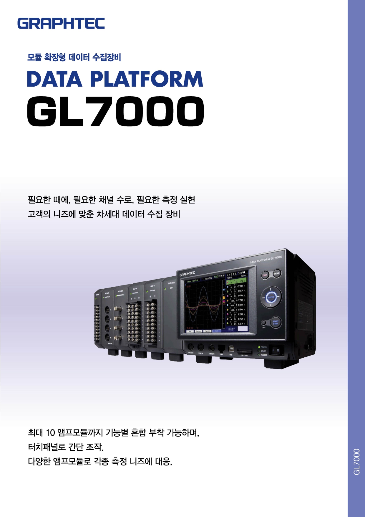
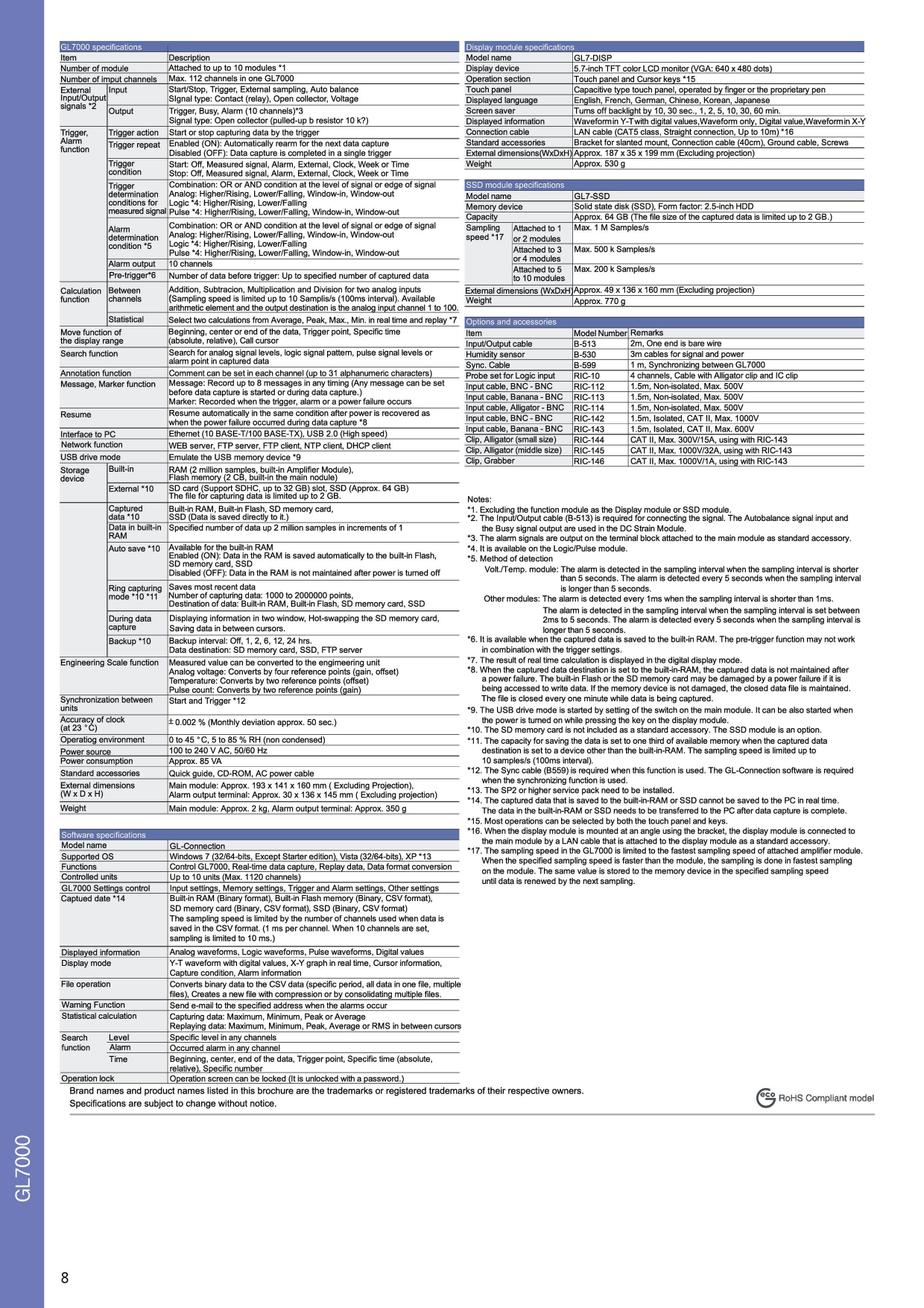
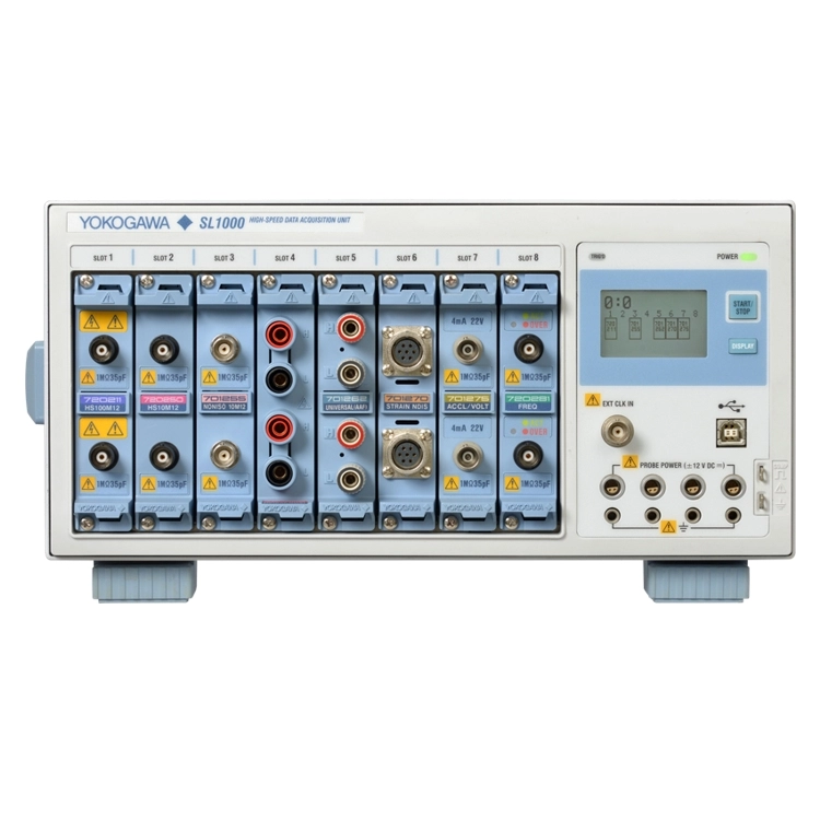
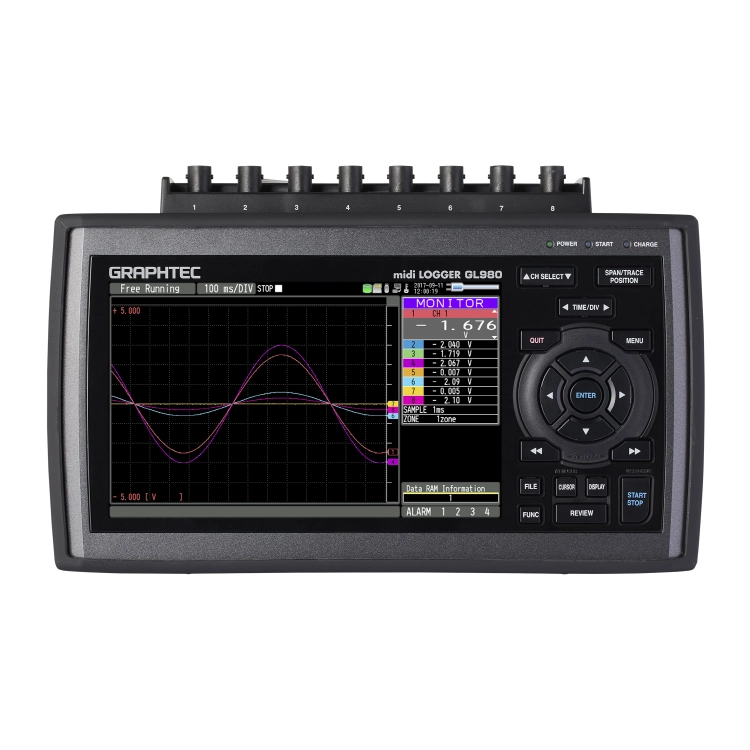
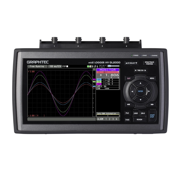
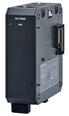
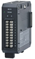
GRAPHTEC 스마트 데이터 수집장비(GL7000)
온도측정, 온도기록, 전압측정, 온습도 데이터수집장치, 레코더, 모니터링, 온도, 전압, 고전압, 고속샘플링, 가속도, 진동, 스트레인게이지, 로직, 펄스, 변형률 측정
- 모듈 추가로 다양한 측정과 채널 확장 (최대 1120CH)
- 측정 모듈 확장에도 동일한 샘플링 속도 유지
- 측정 시그날: 전압, 온도, Logic/pulse 모듈
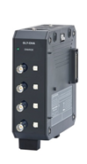
- 탈부착 가능한 5.7인치VGA 디스플레이 모니터
- STAND ALONE 또는 시스템 설비화 가능
- 측정 Application에 맞는 데이터 저장 위치 선택 가능

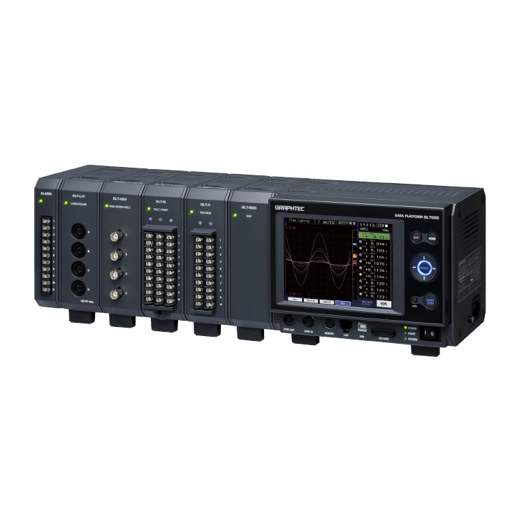
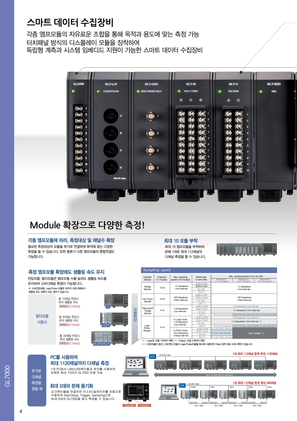
스마트 데이터 수집장비
각종 앰프모듈의 자유로운 조합을 통해 목적과 용도에 맞는 측정 가능
터치패널 방식의 디스플레이 모듈을 장착하여 독립형 계측과 시스템 임베디드 지원이 가능한 스마트 데이터 수집장비
특징 1 - Module 확장으로 다양한 측정!
각종 앰프모듈에 따라, 측정대상 및 채널수 확장
필요한 측정대상의 모듈을 추가로 연결하여 목적에 맞는 다양한 측정을 할 수 있습니다. 또한 종류가 다른 앰프모듈의 혼합연결도 가능합니다.
측정 앰프모듈 확장에도 샘플링 속도 유지
전압모듈, 멀티모듈은 앰프모듈 수를 늘려도 샘플링 속도를 유지하여 고속다채널 측정이 가능합니다.
최대 10 개의 모듈 부착
메인 본체 한 대에 최대 10 개의 앰프모듈을 부착하여 최대 112채널의 다채널 측정을 할 수 있습니다.
측정 앰프모듈 확장에도 샘플링 속도 유지
전압모듈*, 멀티모듈은 앰프모듈 수를 늘려도 샘플링 속도를 유지하여 고속다채널 측정이 가능합니다.
* 고속전압모듈, Logic/Pulse 모듈은 샘플링 속도 제한이 되는 경우가 있습니다.
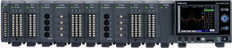
추가로 다채널 측정을 원할 때
PC를 사용하여 최대 1120채널까지 다채널 측정
1대 PC에서 LAN / USB 케이블과 허브를 사용하면 S/W로 최대 10대의 GL7000 연결 가능
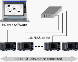
최대 5대의 본체 동기화
싱크케이블을 연결하면 마스터 / 슬레이브를 자동으로 식별하여 Start/Stop, Trigger, Sampling으로 최대 5대의 GL7000을 동시 측정할 수 있습니다
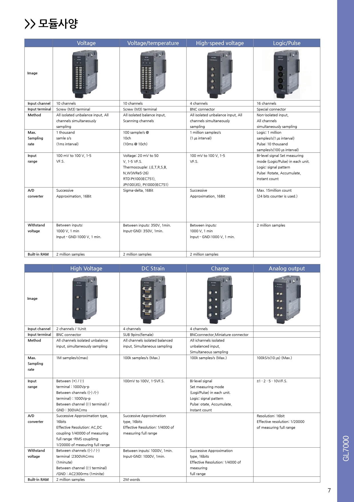
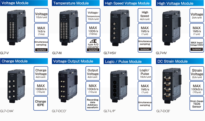
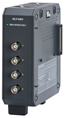
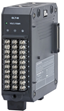
특징 2 - 다양한 신호의 동시 계측 가능!
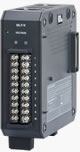
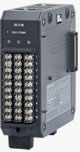
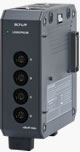
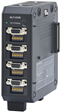
Volt module | Voltage/temperature | High-speed voltage | Logic / Pulse | |
Image |
|
|
|
|
Input channel | 10 channels | 10 channels | 4 channels | 16 channels |
Input terminal | Screw (M3) terminal | Screw (M3) terminal | BNC connector | Special connector |
Method | All isolated unbalance input, | All isolated balace input, | All isolated unbalance input, | Non-isolated input, |
Max. Sampling rate | 1 thousand samples/s | 100 samples/s @ 10ch | 1 million samples/s | Logic:1 million sample/s |
Input range | 100 mV to 100V, 1-5V F.S | Voltage:20mV to 50V, 1-5V F.S | 100mV to 100V, 1-5V F.S | Bi-level signal |
A/D converter | Sucessive Approximation 16 Bit | Sigma-delta, 16 Bit | Successive Approximation, 16Bit | Max. 15 million count |
Withstand voltage | Between inputs: 1000V, 1min. | Betwwen inputs: 350V, 1min. | Between inputs: 1000V, 1min | - |
Built-in RAM | 2 million samples | 2 million samples | 2 million samples | 2 million samples |

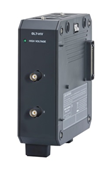
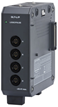
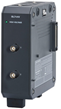
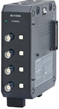
High Voltage module | DC Strain Module | Charge Module | |
Image |
|
|
|
Input channel | 2 channels / 1units | 4channels/ 1unit | 4channels/1unit |
Input terminal | BNC Connector | SUB 9 pins (female) | BNC connector, Miniature connector |
Method | All channels isolated unbalanced input, | All channels isolated balanced input, | All cahnnels isolated unbalanced input, Simultaneous sampling |
Max. Sampling rate | 1M samples/s(max) | 100k samples/s(max) | 100k samples/s(max) |
Input range | Between (+)/(-) | 100mV to 100v, 1-5 V F.S | Bi-level signal |
A/D converter | Successive Approximation type, | Successive Approximation type, 16 bits | Successive Approximation type, 16bits |
Withstand voltage | Between channels ((-)/(-) terminal) 2300VACrms (1minute) | Between inputs: 1000 V, 1min. | |
Built-in RAM | 2M words (8M bite) / 4bite=1 word | 2M words |

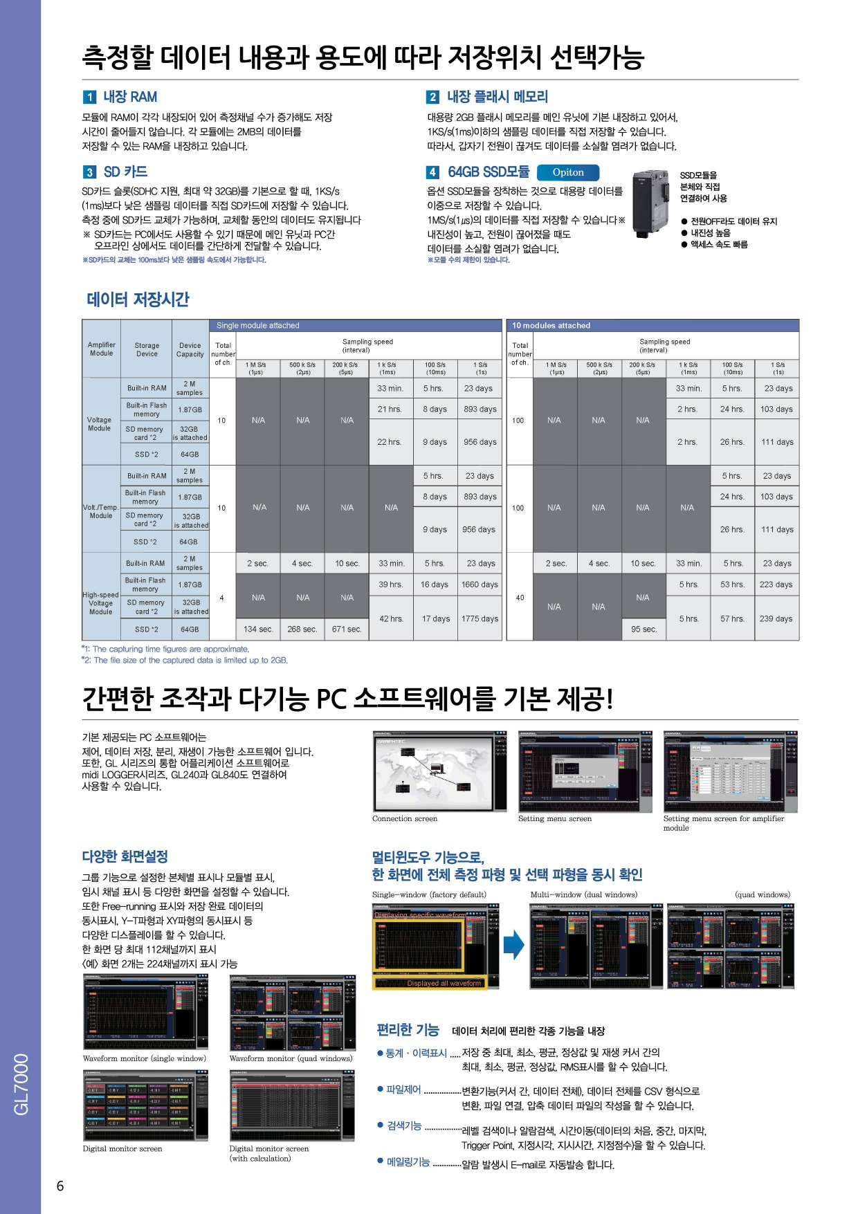
특징 3 - 측정할 데이터 내용과 용도에 따라 저장 위치 선택 가능
1. 내장 RAM
각 모듈에는 2MB의 데이터를 저장할 수 있는 RAM이 각각 내장되어 있어 측정채널 수가 증가해도 저장 시간이 감소하지 않습니다.
2. 내장 플래시 메모리
메인 유닛에 대용량 2GB 플래시 메모리가 내장되어 있어, 1KS/s(1ms)이하의 샘플링 데이터를 직접 저장할 수 있습니다.
따라서, 갑자기 전원이 끊겨도 데이터를 소실할 염려가 없습니다.
3. SD 카드
SD카드 슬롯 (SDHC 지원, 최대 약 32GB)을 기본으로 할 때, 1KS/s(1ms)이하의 샘플링 데이터를 직접 SD 카드에 저장할 수 있습니다.
측정중에 Sd카드 교체가 가능하며, 교체할 동안의 데이터도 유지됩니다.
*SD카드는 PC에서도 사용할 수 있기 때문에 메인 유닛과 PC간 오프라인 상에서도 데이터를 간단하게 전달할 수 있습니다.
*SD카드의 교체는 100ms 이하의 샘플링 속도에서 가능합니다.
4. 64GB SSD모듈 (옵션)
옵션 SSD모듈을 장착하여 대용량 데이터를 이중으로 저장할 수 있습니다.
1MS/s(us)의 데이터를 직접 저장할 수 있습니다.
*내진성이 높고, 전원이 끊어졌을 때도 데이터를 소실할 염려가 없습니다.
*모듈 수의 제한이 있습니다.
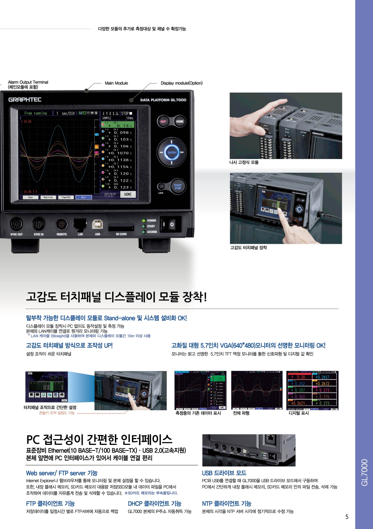
특징 4 - PC접근이 간편한 인터페이스
표준장비 Ethernet (10 BASE-T / 100 BASE-TX) - USV 2.0 (고속지원)
본체 앞면에 PC 인터페이스가 있어서 케이블 연결 편리
Web server / FTP server 기능
Internet Explorer나 웹브라우저를 통해 모니터링 및 본체 설정을 할 수 있습니다.
또한, 내장 플래시 메모리, SD카드 메모리 대용량 저장 SSD모듈 내 데이터 파일을 PC에서 조작하여 데이터를 자유롭게 전송 및 삭제할 수 있습니다.
*SD카드 메모리는 부속품입니다.
FTP 클라이언트 기능
저장데이터를 일정시간 별로 FTP 서버에 자동으로 백업
특징 5 - 고감도 터치패널 디스플레이 모듈 장착
탈부착 가능한 디스플레이 모듈로 Stand-alone 및 시스템 설비화 OK!
디스플레이 모듈 장착시 PC 없이도 동작설정 및 측정 가능
본체와 LAN 케이블 연결로 원거리 모니터링 가능
*CAN 케이블 (straight)을 사용하여 본체와 디스플레이 모듈간 10m 이상 사용
고감도 터치패널 방식으로 조작성 UP!
설정 조작이 쉬운 터치패널
핸디 타입 데이터로거 GL시리즈 (GL220/GL820)와 같은 콘솔키로 조작 가능
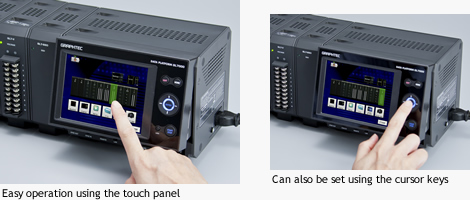
고화질 대형 5.7인치 VGA(640*480)모니터의 선명한 모니터링 OK!
모니터는 밝고 선명한 5.7인치 TFT 액정 모니터를 통한 신호파형 및 디지털 값 확인

간편한 조작과 다기능 PC 소프트웨어를 기본제공!
기본 제공되는 PC 소프트웨어는 제어, 데이터 저장, 분리, 재생이 가능한 소프트웨어 입니다.
또한, GL시리즈의 통합 어플리케이션 소프트웨어로 midi LOGER시리즈, GL220과 GL820도 연결하여 사용할 수 있습니다.
소프트웨어에서의 다양한 화면설정
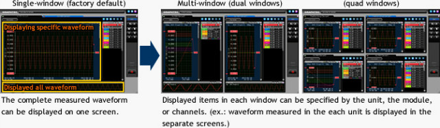
그룹 기능으로 설정한 본체별 표시나 모듈별 표시, 임시 채널 표시 등 다양한 화면을 설정할 수 있습니다.
또한 Free-running 표시와 저장 완료 데이터의 동시표시, Y-T파형과 XY파형의 동시표시 등 다양한 디스플레이를 할 수 있습니다. 한 화면 당 최대 112채널까지 표시
<예> 화면 2개는 224 채널까지 표시 가능
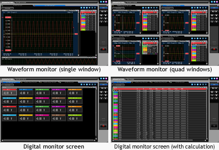
멀티윈도우 기능으로 한 화면에 전체 측정 파형 및 지정 파형을 동시 확인
특징 6 - 편리한 기능 - 데이터 처리에 편리한 각종 기능을 내장
• 통계 이력 표시 ........저장 중 최대, 최소, 평균, 정상값 및 재생 커서 간의 최대, 최소, 평균 정상값, RMS 표시를 할 수 있습니다.
• 파일제어.................변환기능 (커서 간, 데이터 전체), 데이터 전체를 CSV 형식으로 변환, 파일 연결, 압축 데이터 파일의 작성을 할 수 있습니다.
• 검색기능.................레벨 검색이나 알람검색, 시간이동(데이터의 처음, 중간, 마지막, Trigger Point, 지정시각, 지시시간, 지정점수)을 할 수 있습니다.
• 메일링기능..............알람 발생 시 E-mail로 자동발송 됩니다.
Modules and External dimensions
Item | Model number | Remarks |
Main Module | GL7000 | GL7000 main controller module (Alarm output terminal is included.) |
Display Module | GL7-DISP | Display and operation module (LCD with touch panel) |
SSD Module | GL7-SSD | Storage (SSD 64GB) |
Voltage Module | GL7-V | Voltage measurement module |
Voltage/Temperature Module | GL7-M | Voltage and temperature measurement module |
High Speed Voltage Module | GL7-HSV | High speed voltage measurement module |
Logic/Pulse Module | GL7-L/P | Logic pattern or pulse count module |
Charge Module | GL7-CHA | Charge and IEPE Vibration sensor |
DC strain input Module | GL7-DCB | Strain gauge and strain sensor module |
Analog output Module | GL7-DCO | Voltage output module |
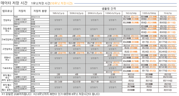
저장처와 앰프유닛 수에 따른 최고 샘플링 속도
샘플링 환산표 | ||||||
앰프유닛 | 1유닛 CH수 | 최고 샘플링 속도 | 저장처 | 최고샘플링 속도 | ||
1~2유닛 사용시 | 3~4유닛 사용시 | 5~10유닛 사용시 | ||||
전압 GL7-V | 10ch | 1KS/s(1ms) | RAM | 1KS/s(1ms) | ||
내장플래시메모리 | ||||||
SD카드 | ||||||
SSD※3 | ||||||
전압/온도 GL7-M | 10ch | 100S/s (10ms) | RAM | 100S/s(10ms) | ||
내장플래시메모리 | ||||||
SD카드 | ||||||
SSD※3 | ||||||
고속전압 GL7-HV | 4ch | 1MS/s (1㎲) | RAM | 1MS/s(1㎲) | ||
내장플래시메모리 | 1KS/s(1ms) | |||||
SD카드 | ||||||
SSD※3 | 1MS/s(1㎲) | 500KS/s(2㎲) | 200KS/s(5㎲) | |||
고전압 GL-HV | 2ch | 1MS/s (1㎲)) | RAM | 1MS/s(1㎲) | ||
내장플래시메모리 | 1KS/s(1ms) | |||||
SD카드 | ||||||
SSD※3 | 1MS/s(1㎲) | 500KS/s(2㎲) | 200KS/s(5㎲) | |||
변형※1 GL7-DCB | 4ch | 100KS/s (10㎲) | RAM | 100KS/s(10㎲) | ||
내장플래시메모리 | 1KS/s(1ms) | |||||
가속도 GL7-CHA | SD카드 | |||||
SSD※3 | 100KS/s(10㎲) | |||||
로직※1 / 펄스 ※1 GL7-L/P | 16ch | 로직 설정시 1MS/s(1㎲) | RAM | 1MS/s(1㎲) | ||
내장플래시메모리 | 1KS/s(1ms) | |||||
SD카드 | ||||||
SSD※3 | 1MS/s(1㎲) | 500KS/s(2㎲) | 200KS/s(5㎲) | |||
펄스 설정시 10KS /s (100㎲)) | RAM | 10KS/s(100us | 측정불가 | |||
내장플래시메모리 | 1KS/s(1ms) | |||||
SD카드 | ||||||
SSD※3 | 10KS/s(100㎲) | |||||
데이터 저장 가능 시간 정리
소프트웨어 무료 다운로드 : http://graphteccorp.com/support/software/instruments.html
추가 옵션 - 별도 구매
Model number | Description |
GL7-DISP | 디스플레이 모듈 |
GL7-SSD | SSD Unit 64GB Solid State Drive 대용량 메모리 모듈 |
GL7-V | Voltage Unit 전압 측정 모듈 |
GL7-HSV | High Speed Voltage Unit 고속전압 측정 모듈 |
GL7-M | Voltage/Temp Unit 전압/온도 측정 모듈 |
GL7-L/P | Logic / Pulse Unit 로직펄스 측정 모듈 |
RIC-10 | Logic / Pulse 모듈용 측정 Probe |
GL7-HV | High Voltage Unit 고전압 측정 모듈 |
GL7-DCB | DC Strain Unit 스트레인게이지 측정 모듈 |
GL7-DCO | DC Output 아날로그 전압출력 모듈 |
GL-CHA | Charge Unit 가속도 / 진동 모듈 |


GL7000 main unit specifications
Item | Description | |
Number of module | Attached to up to 10 modules *1 | |
Number of input channels | Max. 112 channels in one GL7000 | |
External Input/Output signals *2 | Input | Start/Stop, Trigger, External sampling, Auto balance |
Output | Trigger, Busy, Alarm (10 channels) *3 | |
Trigger, Alarm function | Trigger repeat | Enabled (ON): Automatically rearm for the next data capture |
Trigger action | Start or stop capturing data by the trigger | |
Trigger condition | Start: Off, Measured signal, Alarm, External, Clock, Week or Time | |
Trigger determination conditions for measured signal | Combination: OR or AND condition at the level of signal or edge of signal | |
Alarm determination condition *5 | Combination: OR or AND condition at the level of signal or edge of signal | |
Alarm output | 10 channels | |
Pre-trigger *6 | Number of data before trigger: Up to specified number of captured data | |
Calculation function | Between channels | Addition, Subtraction, Multiplication and Division for two analog inputs (Sampling speed is limited up to 10 Samples/s (100ms interval). Available arithmetic element and the output destination is the analog input channel 1 to 100.) |
Statistical | Select two calculations from Average, Peak, Max., Min. in real time and replay *7 | |
Move function of the display range | Beginning, center or end of the data, Trigger point, Specific time (absolute, relative), Call cursor | |
Search function | Search for analog signal levels, logic signal pattern, pulse signal levels or alarm point in captured data | |
Annotation function | Comment can be set in each channel (up to 31 alphanumeric characters) | |
Message, Marker function | Message: Record up to 8 messages in any timing (Any message can be set before data capture is started or during data capture.)Marker: Recorded when the trigger, alarm or power failure occur | |
Resume | Resume automatically in the same condition after power is recovered when the power failure occurred duaring data capture *8 | |
Interface to PC | Ethernet (10 BASE-T/100 BASE-TX), USB 2.0 (High speed) | |
Network function | WEB server, FTP server, FTP client, NTP client, DHCP client | |
USB drive mode | Emulate the USB memory device *9 | |
Storage device | Built-in | RAM (2 million samples, built-in Signal conditioning module), Flash memory (2 gigabytes, built-in the main module) |
External *10 | SD card (Support SDHC, up to 32 GB) slot, SSD (Approx. 64 GB)The file for capturing data is limited up to 2 GB. | |
Data saving function | Captured data *10 | Built-in RAM, Built-in Flash, SD memory card, SSD (Data is saved directly to it.) |
Data in built-in RAM | Specified number of data up 2 million samples increment of 1 | |
Auto save *10 | Available for the built-in RAM | |
Ring capturing mode *10 *11 | Saves most recent data | |
During capturing data | Displaying information in two windows, Hot-swapping the SD memory card, Saving data in between cursors. | |
Backup *10 | Backup interval: Off, 1, 2, 6, 12, 24 hrs. | |
Engineering Scale function | Measured value can be converted to the engineering unit | |
Synchronization between units | Start and Trigger *12 | |
Accuracy of clock (at 23 degree Celsius) | +/- 0.002 % (Monthly deviation approx. 50 sec.) | |
Operating environment | 0 to 45 ºC, 5 to 85 % RH (non condensed) | |
Power source | 100 to 240 V AC, 50/60 Hz | |
Power consumption | Approx. 85 VA | |
Standard accessories | Quick guide, CD-ROM, AC power cable | |
External dimensions (W x D x H) | Main module: Approx. 193 x 141 x 160 mm (Excluding projectin), Alarm output terminal: Approx. 30 x 136 x 145 mm (Excluding projection) | |
Weight | Main module: Approx. 2 kg, Alarm output terminal: Approx. 350 g | |
Display module specifications
Model name | GL-Connection | |
Supported OS | Windows 7 (32/64-bits, Except Starter edition), Vista (32/64-bits), XP *13 | |
Functions | Control GL7000, Real-time data capture, Replay data, Data format conversion | |
Controlled units | Up to 10 units (Max. 1120 channels) | |
GL7000 Settings control | Input settings, Memory settings, Trigger and Alarm settings, Other settings | |
Captured data *14 | Built-in RAM (Binary format), Built-in Flash memory (Binary, CSV format), SD memory card (Binary, CSV format), SSD (Binary, CSV format) | |
Displayed information | Analog waveforms, Logic waveforms, Pulse waveforms, Digital values | |
Display mode | Y-T waveform with digital values, X-Y graph in real time, Cursor information, Capture condition, Alarm information | |
File operation | Converts binary data to the CSV data (specific period, all data in one file, multiple files), Creates a new file with compression or by consolidating multiple file. | |
Warning Function | Send e-mail to the specified address when the alarms occur | |
Statistical calculation | Capturing data: Maximum, Minimum, Peak or Average | |
Search function | Level | Specific level in any channel |
Alarm | Occurred alarm in any channel | |
Time | Beginning, center, end of the data, Trigger point, Specific time (absolute, relative), Specific number | |
Operation lock | Operation screen can be locked (It is unlocked with the password.) | |
Display module specifications
Model name | GL7-DISP | |
Display device | 5.7-inch TFT color LCD monitor (VGA: 640 x 480 dots) | |
Operation section | Touch panel and Cursor keys *15 | |
Touch panel | Capacitive type touch panel, Operated by finger or the proprietary pen | |
Displayed language | English, French, German, Chinese, Korean, Japanese | |
Screen saver | Turns off backlight by 10, 30 sec., 1, 2, 5, 10, 30, 60 min. | |
Displayed information | Waveform in Y-T with digital values, Waveform only, Digital value, Waveform in X-Y | |
Connection cable | LAN cable (CAT5 class, Straight connection, Up to 10m) *16 | |
Standard accessories | Bracket for slanted mount, Connection cable (40cm), Ground cable, Screws | |
External dimensions (W x D x H) | Approx. 187 x 35 x 199 mm (Excluding projection) | |
Weight | Approx. 530 g | |
SSD module specifications
Model name | GL7-SSD | |
Memory device | Solid state disk (SSD), Form factor: 2.5-inch HDD | |
Capacity | Approx. 64 GB (The file size of the captured data is limited up to 2 GB.) | |
Sampling speed *17 | Attached 1 or 2 modules | Max. 1 M Samples/s |
Attached 1 or 2 modules | Max. 500 k Samples/s | |
Attached 5 to 10 modules | Max. 200 k Samples/s | |
External dimensions (W x D x H) | Approx. 49 x 136 x 160 mm (Excluding projection) | |
Weight | Approx. 770 g | |
*1
Excluding the function module as the Display module or SSD module.
*2
The Input/Output cable (B-513) is required for connecting the signal. The Autobalance signal input and the Busy signal output are used in the DC Strain Module.
*3
The alarm signals are output on the terminal block attached to the main module as standard accessory.
*4
It is available on the Logic/Pulse module.
*5
Method of detection Volt./Temp. module: The alarm is detected in the sampling interval when the sampling interval is shorter than 5 seconds. The alarm is detected every 5 seconds when the sampling interval is longer than 5 seconds. Other modules: The alarm is detected in every 1ms when the sampling interval is shorter than 1ms. The alarm is detected in the sampling interval when the sampling interval is set between 2ms to 5 seconds. The alarm is detected every 5 seconds when the sampling interval is longer than 5 seconds.
*6
It is available when the captured data is saved to the built-in RAM. The pre-trigger function may not work in combination with the trigger settings.
*7
The result of real time calculation is displayed in the digital display mode.
*8
When the captured data destination is set to the built-in-RAM, the captured data is not maintained after a power failure occur. The built-in Flash or the SD memory card may be damaged by a power failure if it being accessed to writ data. If the memory device is not damaged, the closed data file is maintained. The file is closed every one minute while data is being captured.
*9
The USB drive mode is started by setting of the switch on the main module. It can be also started when the power is turned on while pressing the key on the display module.
*10
The SD memory card is included as the standard accessory. The SSD module is an option.
*11
The capacity for saving the data is set to one third of available memory when the captured data destination is set to a device other than the built-in-RAM. The sampling speed is limited up to 10 samples (100ms interval).
*12
The Sync cable (B559) is required when this function is used. The GL-Connection software is required when the synchronizing function is used.
*13
The SP2 or higher service pack need to be installed.
*14
The captured data that is saved to the built-in-RAM or SSD cannot be saved to the PC in real time. The data in built-in-RAM or SSD needs to be transferred to the PC after data captur is complete.
*15
Most operations can be selected by both touch panel and keys.
*16
When the display module is mounted at an angle using the bracket, the display module is connected to the main module by a LAN cable that is attached to the display module as standard accessory.
*17
The sampling speed in the GL7000 is limited to the fastest sampling speed of attached signal conditioning module. When the specified sampling speed is faster than the module, the sampling is done in fastest sampling on the module. The same value is stored to the memory device in the specified sampling speed until data is renewed by the next sampling.
Voltage/Temperature Module Specifications
Model number | GL7-M | ||||
Number of input channels | 10 channels | ||||
Input method | All channels isolated balanced input, Scans channels for sampling, Screw terminal (M3 screw) | ||||
Sampling speed | 100 Samples/s at 1-10ch to 1 Sample/h (10 ms with 1-10ch to 1 hr. interval) | ||||
Measurement range | Voltage | 20, 50, 100, 200, 500 mV, 1, 2, 5, 10, 20, 50 V, and 1-5 V/F.S. | |||
Temperature | Thermocouple: K, J, E, T, R, S, B, N, and W (WRe5-26), | ||||
Humidity *1 | 0 to 100 % (using scaling function in 5V range, humidity sensor B-530) | ||||
Measurement accuracy*2 | Voltage | ± 0.1 % of F.S. | |||
Temperature | Thermocouple | Measurement range | Measurement accuracy | ||
R/S | 0 °C ≤ TS ≤ 100 °C | ± 5.2 °C | |||
100 °C < TS ≤ 300 °C | ± 3.0 °C | ||||
R: 300 °C < TS ≤ 1600 °C | ± (0.05 % of reading + 2.0 °C) | ||||
S: 300 °C < TS ≤ 1760 °C | ± (0.05 % of reading + 2.0 °C) | ||||
B | 400 °C ≤ TS ≤ 600 °C | ± 3.5 °C | |||
600 °C < TS ≤ 1820 °C | ± (0.05 % of reading + 2.0 °C) | ||||
K | -200 °C ≤ TS ≤ -100 °C | ± (0.05 % of reading + 2.0 °C) | |||
-100 °C < TS ≤ 1370 °C | ± (0.05 % of reading + 1.0 °C) | ||||
E | -200 °C ≤ TS ≤ -100 °C | ± (0.05 % of reading + 2.0 °C) | |||
-100 °C < TS ≤ 800 °C | ± (0.05 % of reading + 1.0 °C) | ||||
T | -200 °C ≤ TS ≤ -100 °C | ± (0.1 % of reading + 1.5 °C) | |||
-100 °C < TS ≤ 400 °C | ± (0.1 % of reading + 0.5 °C) | ||||
J | -200 °C ≤ TS ≤ -100 °C | ± 2.7 °C | |||
-100 °C < TS ≤ 100 °C | ± 1.7 °C | ||||
100 °C < TS ≤ 1100 °C | ± (0.05 % of reading + 1.0 °C) | ||||
N | 0 °C ≤ TS ≤ 1300 °C | ± (0.1 % of reading + 1.0 °C) | |||
W | 0 °C ≤ TS ≤ 2000 °C | ± (0.1 % of reading + 1.5 °C) | |||
Reference Junction Compensation (R.J.C.) accuracy: ± 0.5 °C *3 | |||||
RTD | Measurement range | Driving current | Accuracy | ||
Pt100 | -200 °C to 850 °C (FS = 1050 °C) | 1 mA | ± 1.0 °C | ||
JPt100 | -200 °C to 500 °C (FS = 700 °C) | 1 mA | ± 0.8 °C | ||
Pt1000 | -200 °C to 500 °C (FS = 700 °C) | 0.2 mA | ± 0.8 °C | ||
R.J. Compensation | Selecting of the internal or external | ||||
A/D Converter | Sigma-Delta type, 16 bits (effective resolution: 1/40000 of measuring full range) | ||||
Stability with temperature | Gain | 0.01 % of F.S./°C | |||
Zero *4 | 0.02 % of F.S./°C | ||||
Input impedance | 1 MΩ ± 5 % | ||||
Maximum input voltage | Between (+) / (-) terminal | 60 V p-p | |||
Between channels | 60 V p-p | ||||
Between channel / GND | 60 V p-p | ||||
Maximum voltage | Between channels | 350 V p-p (1 minute) | |||
Between channel / GND | 350 V p-p (1 minute) | ||||
Isolation | Between input / GND | Min. 50 MΩ (at 500 V DC) | |||
Common-mode rejection ratio | Min. 90 dB (50/60 Hz, Signal source impedance: Max. 300 Ω) | ||||
Filter | Off, 2, 5, 10, 20, 40 (Moving average in selected number. When the sample is longer than 5 seconds, the data sampled in the sub-sample (5 seconds) will be used for creating the average value. ) | ||||
5V output | Driving the humidity sensor B-530, 1 channel | ||||
External dimensions (W×D×H) | 49 x 136 x 160 mm (Excluding projection) | ||||
Weight | Approx. 770 g | ||||
Voltage module specifications
Voltage module specifications | Voltage | High Speed Voltage | |
Model number | GL7-V | GL7-HSV | |
Number of input channels | 10 channels | 4 channels | |
Input method | All channels isolated unbalanced input, Simultaneous sampling, Screw terminal | All channels isolated unbalanced input, Simultaneous sampling, BNC connector | |
Sampling speed (interval) | 1 k Samples/s to 1 Sample/h (1ms to 1h) | 1 M Samples/s to 1 Sample/h (1μs to 1h) | |
Measurement range | 100, 200, 500 mV,1, 2, 5, 10, 20, 50, 100 V, and 1-5 V/F.S. | ||
Measurement accuracy*5 | ± 0.25 % of F.S. | ||
A/D Converter | Successive Approximation type, 16 bits (effective resolution: 1/40000 of measuring full range) | ||
Stability with temperature | Gain | 0.01 % of F.S./°C | |
Zero | 0.02 % of F.S./°C | ||
Input impedance | 1 MΩ ± 5 % | ||
Maximum input voltage | Between (+) / (-) terminal | 100mV to 1V range: 60 V p-p, 2V to 100V range: 100 V p-p | |
Between channels | 60 V p-p | ||
Between channel / GND | 60 V p-p | ||
Maximum voltage | Between channels | 1000 V p-p (1 minute) | |
Between channel / GND | 1000 V p-p (1 minute) | ||
Isolation | Between input / GND | Min. 50 MΩ (at 500 V DC) | |
Common-mode rejection ratio | Min. 90 dB (50/60 Hz, Signal source impedance: Max. 300 Ω) | ||
Frequency response | DC to 1 k Hz (at +1/-3 dB) | DC to 2 k Hz (at +1/-3 dB) | |
Filter (Low pass) | Off, Line(1.5Hz), 5, 50, 500 Hz (-3dB, 6dB/oct) | Off, Line(1.5Hz), 5, 50, 500, 5k, 50k Hz (at -3dB, 6dB/oct) | |
External dimensions (W×D×H) | 49 x 136 x 160 mm (Excluding projection) | ||
Weight | Approx. 840 g | Approx. 740 g | |
Logic/Pulse Module Specifications
Model number | GL7-L/P | |
Number of input channels | 16 channels | |
Input method | All channels common ground, simultaneous sampling, Circular connector (4ch/connector) | |
Sampling speed | Logic mode | Up to 1 M Samples/s (1μs interval) |
Pulse mode | Up to 10 k Samples/s (100μs interval) | |
Measurement mode | Selecting of the Logic input mode or Pulse input mode *6 | |
Mode | Pulse | Rotation count (RPM), Accumulating count, Instant count |
Rotation count (RPM) | Function | Counting the number of pulses per sampling interval and then it is converted to RPM |
Range | 50, 500, 5000, 50 k, 500 k, 5 M, 50 M, 500 M rpm/F.S. | |
Accumulating count | Function | Accumulating the number of pulses from the start of measurement |
Range | 50, 500, 5 k, 50 k, 500 k, 5 M, 50 M, 500 M counts/F.S. | |
Instant count | Function | Counting the number of pulses per sampling interval (count is reset at each sampling) |
Range | 50, 500, 5 k, 50 k, 500 k, 5 M, 50 M, 500 M counts/F.S. | |
Max. input frequency | 1 M Hz | |
Max. number of count | 15 M counts (24 bits counter is used) | |
Input signal | Voltage range | 0 to +24 V (common ground) |
Signal type | Contact (Relay), Open collector, Voltage | |
Threshold | Approx. 2.5 V | |
Hysteresis | Approx. 0.5 V (2.5 V to 3 V) | |
Filter | Off or On (-3 dB at 50 Hz) | |
External dimensions (W×D×H) | 49 x 136 x 160 mm (Excluding projection) | |
Weight | Approx. 700 g | |
*1
Using optional humidity sensor (B-530).
*2
Subject to the following conditions;
- Room Temperature is 23°C ±5°C
- When 30 minutes or more have elapsed after power was turned on.
- Filter is set to 10.
- Sampling rate is set to 1s with 10 channels.
- GND terminal is connected to ground.
*3
Wire size of thermocouple to use is 0.32mm in T type, 0.65mm in other type.
*4
It is effective when the 10, 20, 50ms sampling is used. When the sampling is slower than 100ms, it is not effective by executing the Zero calibration periodically.
*5
Subject to the following conditions;
- Room Temperature is 23°C ±5°C.
- When 30 minutes or more have elapsed after power was turned on.
- Filter is set to Line (1.5 Hz).
- Sampling rate is set to 1s.
- GND terminal is connected to ground
*6
The measuring mode is set in each module (16 channels). When the module is used in the Logic, up to 7 modules can be attached to one main module. (max. 112 ch) When the module is used in the Pulse, up to 2 modules can be attached to one main module. (max. 32 ch) The amplifier module can be attached to up to 10 modules. The maximum number of channels is limited to up to 112 channels.